PLCT
PLCT
rtt_dts

rtt的设备树通过online package(fdt)来支持,但已经2年没更新了
另有两年前的讨论指出当时的dts并不好用
fdt依赖于文件系统,编译可能不过

目前最全免得介绍位于smart文档中
/ {
    // 表示子结点的地址相关值占一个 32 位整数的 cell
    #address-cells = <1>;
    // 表示子结点的大小相关值占一个 32 位整数的 cell
    #size-cells = <1>;
    // 表示设备兼容 "my-hardware" 的特性
    compatible = "my-hardware";
    // 设备模型,仅用于为用户提供设备信息
    model = "My Hardware Platform";

    // 使用 ttyS0 作为控制台输入输出设备,波特率 115200,并将 "/dev/mmcblk0p2" 块设备上的 VFAT 文件系统挂载到根目录。
    chosen {
        bootargs = "console=ttyS0,115200 root=/dev/mmcblk0p2 rw rootfstype=vfat";
    };

    // 指定可用物理内存范围
    memory@0x0 {
        // 必须显式指定该属性值为 "memory"
        device_type = "memory";
        reg = <0x0 0x10000000>; // 1GB of RAM starting at address 0x0
    };

    cpus {
        // cpus 的该属性必须是 0x0
        #size-cells = <0x0>;
        #address-cells = <0x1>;

        cpu@0 {
            reg = <0x0>;
            enable-method = "psci";
            compatible = "arm,cortex-a53";
            // cpu 节点必须指定 device_type 为 "cpu"
            device_type = "cpu";
        };

        cpu@1 {
            reg = <0x1>;
            enable-method = "psci";
            compatible = "arm,cortex-a53";
            device_type = "cpu";
        };
    };

    reserved-memory {
        // 指定地址单元格的数量
        #address-cells = <1>;
        // 指定大小单元格的数量
        #size-cells = <1>;
        // 表示将 reserved-memory 结点下以 0x0 开始的地址长度 0x100 映射到 cpu 的 0x10000 地址
        ranges = <0x0 0x10000 0x100>;

        // 内存区域的名称
        framebuffer@30000000 {
            compatible = "my_reserved_memory";
            // 内存区域的地址和大小。根据父结点的 ranges,其映射到 cpu 地址空间的 0x10000
            reg = <0x0 0x100>;
        };
    };

    // 指定上面的内存结点别名为 mem
    aliases {
        mem = &/memory@0x0;
    };

    // 其他结点如果想引用内存结点,可以不必提供完整路径
    other-region {
        memory-device = <&mem>
    }

    intc@8000000 {
        // 中断控制器使用的内存
        reg = <0x0 0x8000000 0x0 0x10000 0x0 0x8010000 0x0 0x10000>;
        compatible = "arm,cortex-a15-gic";
        interrupt-controller;
        #interrupt-cells = <0x3>;
    };

    // 一个设备示例
    my-device {
        // 用于与驱动配对
        compatible = "my-device";
        // IO 资源
        reg = <0x0 0x1000>;
        // 向该中断控制器发送中断请求
        interrupt-parent = <&/intc@8000000>;
        // 中断资源,格式由对应中断控制器的 #interrupt-cells 控制
        interrupts = <0x0 0x1 0x2>;
    };
};
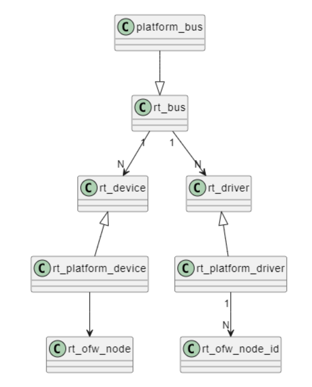
大致原理:与linux类似,均采用了平台总线设备的结构。平台总线platform_bus继承自rt_bus,平台设备rt_platform_device继承自rt_device,平台驱动rt_driver继承自rt_platform_driver

设备与驱动绑定方法与linux类似:均通过compatible属性实现:当设备与驱动的compatible相同时,rtt内核会通过字符处理来解析设备树文件:
int fdt_node_check_compatible(const void *fdt, int nodeoffset,
			      const char *compatible)
{
	const void *prop;
	int len;

	prop = fdt_getprop(fdt, nodeoffset, "compatible", &len);
	if (!prop)
		return len;

	return !fdt_stringlist_contains(prop, len, compatible);
}
判断节点也是通过字符处理
static int _fdt_nodename_eq(const void *fdt, int offset,
			    const char *s, int len)
{
	const char *p = fdt_offset_ptr(fdt, offset + FDT_TAGSIZE, len+1);

	if (! p)
		/* short match */
		return 0;

	if (memcmp(p, s, len) != 0)
		return 0;

	if (p[len] == '\0')
		return 1;
	else if (!memchr(s, '@', len) && (p[len] == '@'))
		return 1;
	else
		return 0;
}
最后在启动阶段时将设备与驱动注册进内核
资源获取方面,可以通过官方的api获取地址和空间
对于io资源:
- 通过
int rt_ofw_io_addr_cells(struct rt_ofw_node *np)获取节点地址数量 - 通过
rt_err_t rt_ofw_get_address(struct rt_ofw_node *np, int index, rt_uint64_t *out_address, rt_uint64_t *out_size)获得节点空间数量 - 或通过
rt_uint64_t rt_ofw_translate_address(struct rt_ofw_node *np, const char *range_type, rt_uint64_t address)获得节点资源 - 上述获得的地址为设备树中抽象出的总线地址,我们还需要使用
rt_uint64_t rt_ofw_translate_address(struct rt_ofw_node *np, const char *range_type, rt_uint64_t address)进行地址转换来获得真实物理地址 - 对于有mmu的处理器来说还需要使用
void *rt_ofw_iomap(struct rt_ofw_node *np, int index)将物理地址转换为虚拟地址